|
|

|
|
|
|
|
|
|
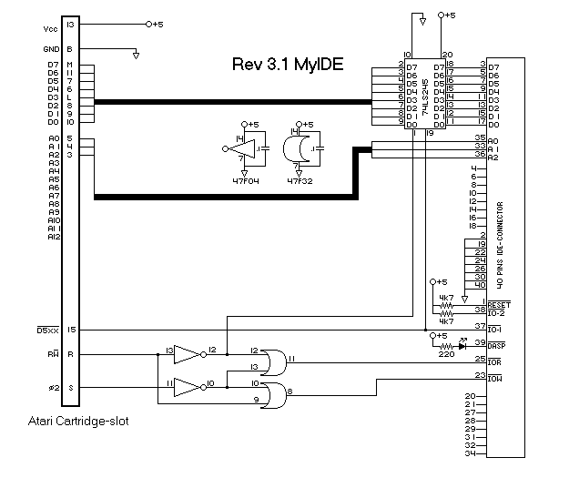
Copyrights: If you can get your hands on 74F04 and 74F32 instead of the LS-types, do buy them. The F-types give 99% compatibility with IDE-drives. With the LS type you need to find a drive that works fine. New version (3.1) on this page. Now it works on more drives! If you made the version 1 or 2 interface, please change the IDE-connector pins 4,6,8,10,12,14,16,18 to: not connected, add a 4k7 Ohm pull-up resistor to pen38 of the IDE-connector, use a 220 Ohm resistor for a activity-led. On this page you see the schematics, example and wire-layout (component-side) to build your own MyIDE-interface. The print has 17 connections you have make. 16 wires go inside your Atari XL/XE or onto a empty cartridge. The print out the pictures: Right click on the picture and select print. Just drop me a line when you need help.
Schematics of Rev 3.1
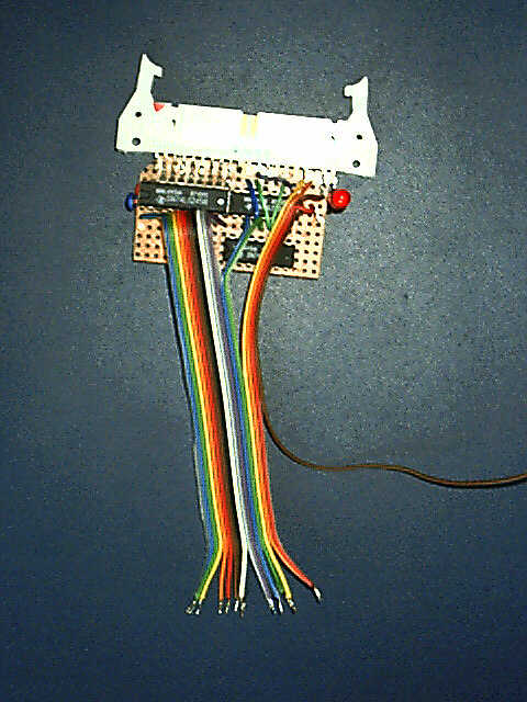
Example of your PCB (top-vieuw)
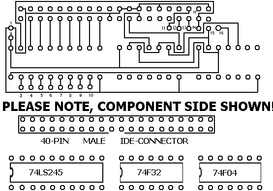
Example of your wiring on your home-made PCB
Use Right-Click on the layout, save picture, print it out the way you want it, and start building! Where to put the components (pin 1 is always bottem left):
Where to connect the 16 wires inside
your ATARI XL/XE: 1 - pin 1 Where to connect the 16 wires onto a empty cartridge: 1 - B Atari cartridge connector (this is how you LOOK at it, NO SOLDER-SIDE): XL XE Back 15 14 13 12 11 10 9 8 7 6 5 4 3 2 1 BOTTOM-ROW | | | | | | | | | | | | | | | +++++++++++++++++++++++++++++++++++++++++++ | | | | | | | | | | | | | | | Front (keyboard) S R P N M L K J H F E D C B A TOP-ROW !!>>>If you use a emptied game-cartridge: remove traces to A and 14 to disable 'ROM' at $8000-$BFFF<<<!!
|